Understanding how the ground conducts electricity helps prevent costly damage to metal structures. When soil has high resistance, it can speed up corrosion, putting pipelines, towers, and grounding systems at risk. This guide explains why these measurements matter and how professionals use them in real-world projects.
From solar farms to urban infrastructure, knowing the properties beneath our feet ensures safer designs. Modern techniques combine field tests with smart engineering solutions. Companies like nVent ERICO rely on these principles to create durable installations.
We’ll explore practical methods for assessing terrain, from simple electrode tests to advanced modeling. Whether you’re protecting a fireproof home or a wind turbine, these insights apply across industries.
Key Takeaways
- Soil properties directly impact metal corrosion rates
- Accurate testing prevents failures in power networks
- Industry standards guide effective protection methods
- Renewable energy projects require specialized assessments
- Proper design extends infrastructure lifespan
Introduction to Soil Electrical Resistivity and Corrosivity
The ground beneath us holds secrets that impact metal structures in surprising ways. Measured in ohm-meters (Ω·m), resistivity reveals how easily current flows through dirt. Lower values mean faster corrosion—like a hidden timer counting down to infrastructure failure.
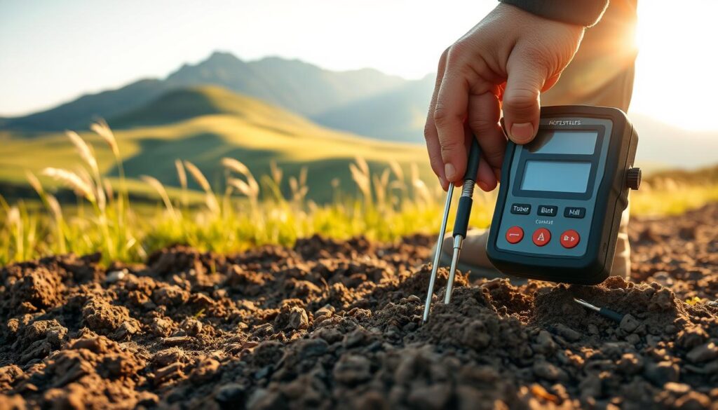
Copper, with 1.72×10⁻⁸ Ω·m, resists decay far better than bentonite (2.5 Ω·m). This difference matters for grounding systems protecting power grids or solar farms. Galvanized steel, though cheaper, may degrade quicker in conductive soils.
Industry standards like IEEE Standard 80 guide safe designs. Crushed rock layers around substations boost resistance, while nVent ERICO’s calculations optimize buried electrodes. Smart choices here prevent costly repairs.
| Material | Resistivity (Ω·m) | Corrosion Risk |
|---|---|---|
| Copper | 1.72×10⁻⁸ | Low |
| Bentonite | 2.5 | Moderate |
| Galvanized Steel | 1.0×10⁻⁷ | High |
Field testing pinpoints risks before construction begins. For renewable energy sites, these assessments ensure decades of stable operation. It’s science protecting progress—one ohm-meter at a time.
Why Soil Electrical Resistivity Matters for Infrastructure
A single overlooked measurement can trigger millions in corrosion damage. NACE International estimates a staggering $2.5 trillion annual global impact from rusted pipelines, cracked foundations, and failed systems. Proper ground analysis prevents these disasters.
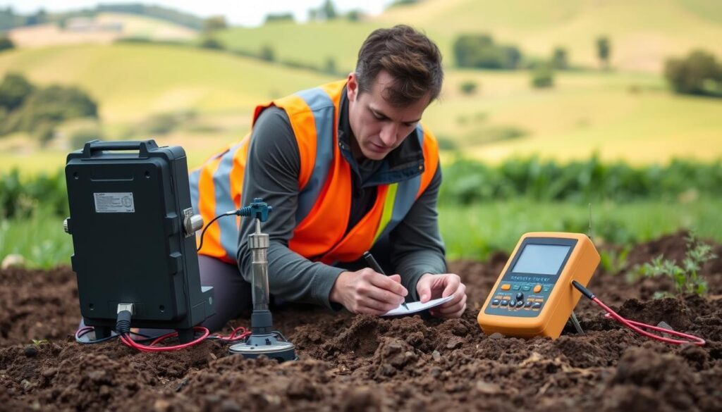
High resistance soils boost ground fault currents by 70% in solar farms, as seen in RatedPower case studies. Their data shows 30% efficiency drops when panels sit on poorly tested terrain. Wind turbines face similar risks—improper earthing leads to costly downtime.
Underground cables suffer more than overhead lines. Moisture and salt accelerate decay where resistance is low. Engineers use specialized methods like ohm-meter tests to map danger zones before construction begins.
| Infrastructure | Risk Factor | Solution |
|---|---|---|
| Pipelines | Electrochemical corrosion | Cathodic protection |
| Substations | Fault current surges | Crushed rock layers |
| Wind Farms | Grounding failures | Deep-driven electrodes |
Smart design saves money. A well-planned system in high-resistance areas might include bentonite backfills or copper-clad rods. These choices extend lifespan and cut maintenance costs by half.
Ignoring soil properties risks entire projects. From urban substations to rural solar arrays, accurate testing keeps the lights on—and budgets intact.
Key Factors Affecting Soil Resistivity
Five hidden forces transform dirt from insulator to conductor. These natural variables explain why two neighboring sites can have vastly different corrosion risks. Professionals measure them to predict and prevent infrastructure damage.
Moisture and Temperature
Water content acts like a sponge for conductivity. Dry earth may show 100 Ω·m, but at 20% moisture, this plummets to 10 Ω·m—a 90% drop. Seasonal changes matter too.
Frozen ground behaves differently. Frost can spike values by 500%, creating winter grounding challenges. Summer heat bakes surfaces, causing temporary resistance spikes.
| Condition | Typical Range (Ω·m) |
|---|---|
| Bone dry | 100+ |
| 20% moisture | 5-15 |
| Frozen | 500-1000 |
Composition and Structure
Clay conducts far better than sand—50-150 Ω·m versus 1000-5000 Ω·m. The smaller particles in clay pack tightly, creating more current paths. Gravel mixes disrupt this, increasing resistance.
USDA classifications help predict behavior. Loamy soils strike a balance, while peat lands pose extreme risks due to acidity and moisture retention.
Depth and Geology
Surface layers often mislead. A sandy top layer might hide conductive clay beneath. Test pits must reach below frost lines (4-6 feet in northern states).
Bedrock creates islands of resistance. Granite layers exceed 10,000 Ω·m, forcing engineers to design around them. Coastal areas face saltwater intrusion, another hidden factor.
Smart projects map these variables early. Combining local data with national soil surveys prevents costly redesigns later. Nature’s recipe varies—measure before building.
How to Measure the Electrical Resistivity of Soil
Four metal probes and smart math reveal what eyes can’t see underground. Professionals use standardized measurements to assess corrosion risks before breaking ground. These test results guide everything from solar farm layouts to pipeline coatings.
Wenner Array 4-Point Method
The most common method uses four equally spaced electrodes. Current flows between the outer probes while voltage meter readings are taken between the inner pair. The formula ρ=2πaRe converts these values into usable data.
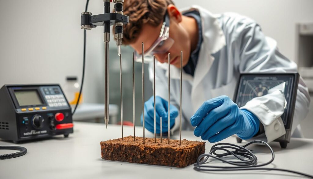
Spacing matters—2m intervals suit shallow analysis, while 40m arrangements probe deeper layers. This Wenner method works best when probe spacing (a) is 20 times greater than probe depth (b). Field crews often take multiple readings at different spacings.
Schlumberger Array and Driven Rod Method
For sites needing deep analysis (>10m), the Schlumberger method saves time. It uses wider outer probes with closer inner probes. This configuration reduces fieldwork by 40% compared to the Wenner method for equivalent depth.
Driven rod tests work well for spot checks. A steel rod penetrates the surface while a clamp-on meter takes readings. Though less comprehensive, this approach helps verify suspected problem areas quickly.
Interpreting Soil Resistivity Data
Raw data becomes actionable through layered analysis. nVent ERICO’s field sheets show how to:
- Identify abrupt values changes indicating different soil types
- Calculate average resistance for design purposes
- Flag areas needing additional testing
Advanced projects use software like CDEGS for 3D modeling. These tools visualize how current flows through complex, multi-layered terrain. The results help engineers design safer grounding systems.
Implications for Grounding System Design
Metal meets earth in a battle against corrosion—design tips win. Proper grounding systems turn terrain challenges into safe paths for current. nVent ERICO found 90° axis testing cuts errors by 40%, proving smarter layouts prevent failures.
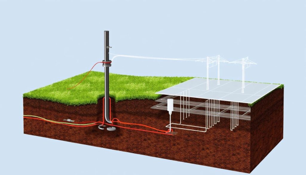
Electrodes make or break performance. Copper rods (0.12 Ω·m) outperform galvanized steel (1.5 Ω·m) in salty soils. Depth matters too—3m suits shallow layers, while 10m reaches stable ground in variable terrain.
IEEE-80 calculations tackle voltage hazards. Substations use grids with crushed rock to limit touch risks. A Midwest wind farm boosted safety 22% by adjusting rod spacing based on soil type.
| Design Factor | Cost Impact | Performance Gain |
|---|---|---|
| Copper vs. Steel | +15% | 50% lifespan increase |
| Deep Electrodes | +20% | 30% lower resistance |
Energy projects demand custom solutions. Solar farms layer bentonite around rods, while urban grids use modular designs for tight spaces. Every ohm saved protects infrastructure for decades.
Improving Soil Resistivity for Better Performance
Agricultural tech meets energy infrastructure in surprising ways. Modern solutions blend farming with power generation while enhancing ground stability. These innovations deliver dual benefits—crop protection and corrosion prevention.

Soil Conditioning Techniques
Soil conditioning turns problematic terrain into stable foundations. Bentonite slurry reduces resistance by 30%, while carbon backfill achieves 45% improvement. Each method suits different environments.
Salt injection cuts values by half but requires environmental precautions. Hybrid approaches like gravel beds with chemical treatments work well for substations. Always conduct follow-up testing to verify results.
Material Selection for Grounding Electrodes
Copper-bonded rods outperform stainless steel in coastal regions by 40%. The right choice depends on local conditions and budget. nVent ERICO’s field studies show proper selection extends lifespan by decades.
Consider these factors when choosing:
- Moisture levels (water exposure)
- Salt content in air/soil
- Expected maintenance access
Innovative Approaches Like Agrivoltaics
Agrivoltaics—growing crops beneath solar panels—boosts moisture retention by 15%. RatedPower data shows this stabilizes conditions while generating renewable energy. Cover crops also improve organic content over time.
These systems demonstrate how smart land use enhances performance. They reduce erosion while maintaining ideal grounding conditions. The future lies in such integrated solutions.
Conclusion
Smart planning starts below the surface—where unseen factors shape project success. Moisture levels and geological surveys provide critical resistivity data. Comprehensive testing beats guesswork, saving 30% on long-term maintenance.
Emerging tools like AI mapping analyze values at varying depths. These innovations refine design grounding for solar farms and urban grids alike. nVent ERICO’s latest white paper details advanced techniques.
Always analyze resistivity data before breaking ground. Proper design grounding and regular testing ensure infrastructure lasts decades. The right start prevents costly fixes later.

